Busdisplay
A small display that shows what's on an 8-bit bus
Background
This project is my first serious PCB project. Actually it is one of my first attempts at using EasyEDA and JLCPCB for PCBs. It is the starting point of my transition from perfboards to prototype PCBs and also inspires me to work in embedded full time.
There are two inspirations for this board, one is my need to debug my various logic chips projects, and another is Julian Ilett's video about his OInK display board. His board uses a 74HC573 latch and a couple of MC14495 binary to 7-segment drivers. MC14495 is an old chip, therefore I want to create a similar board with a microcontroller instead.
Note: The PCB for this project was sponsored by PCBWAY using the 2L HASL Lead Free specifications. You may order this board for yourself at this link.
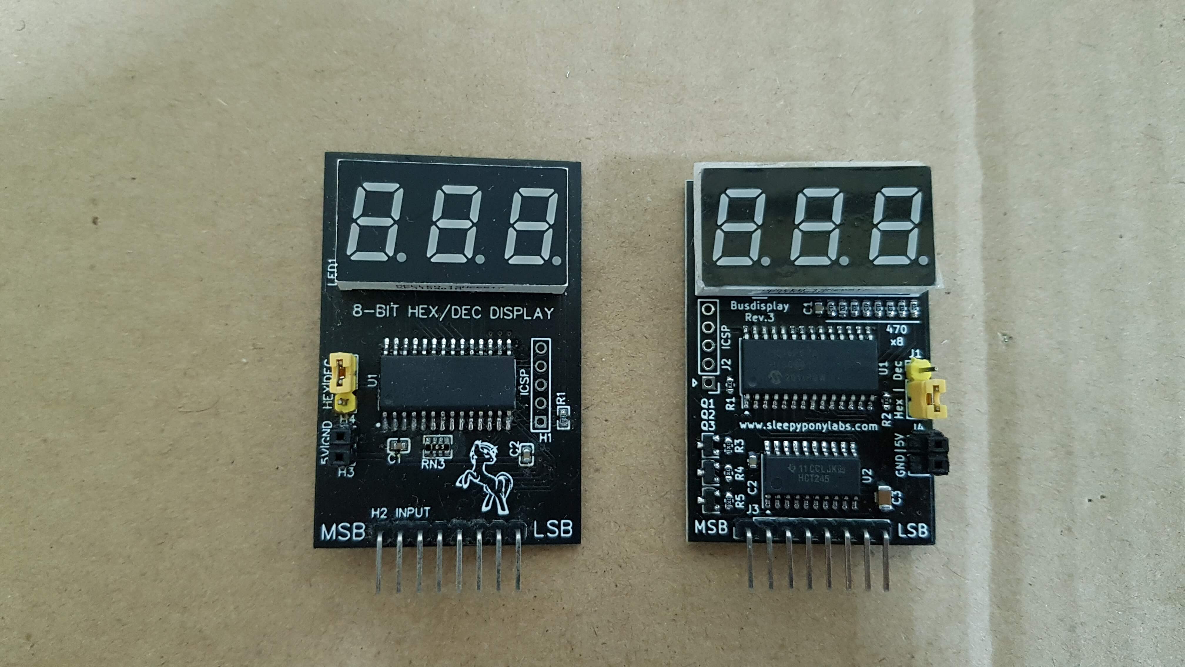
First Revision (Jan 2020)
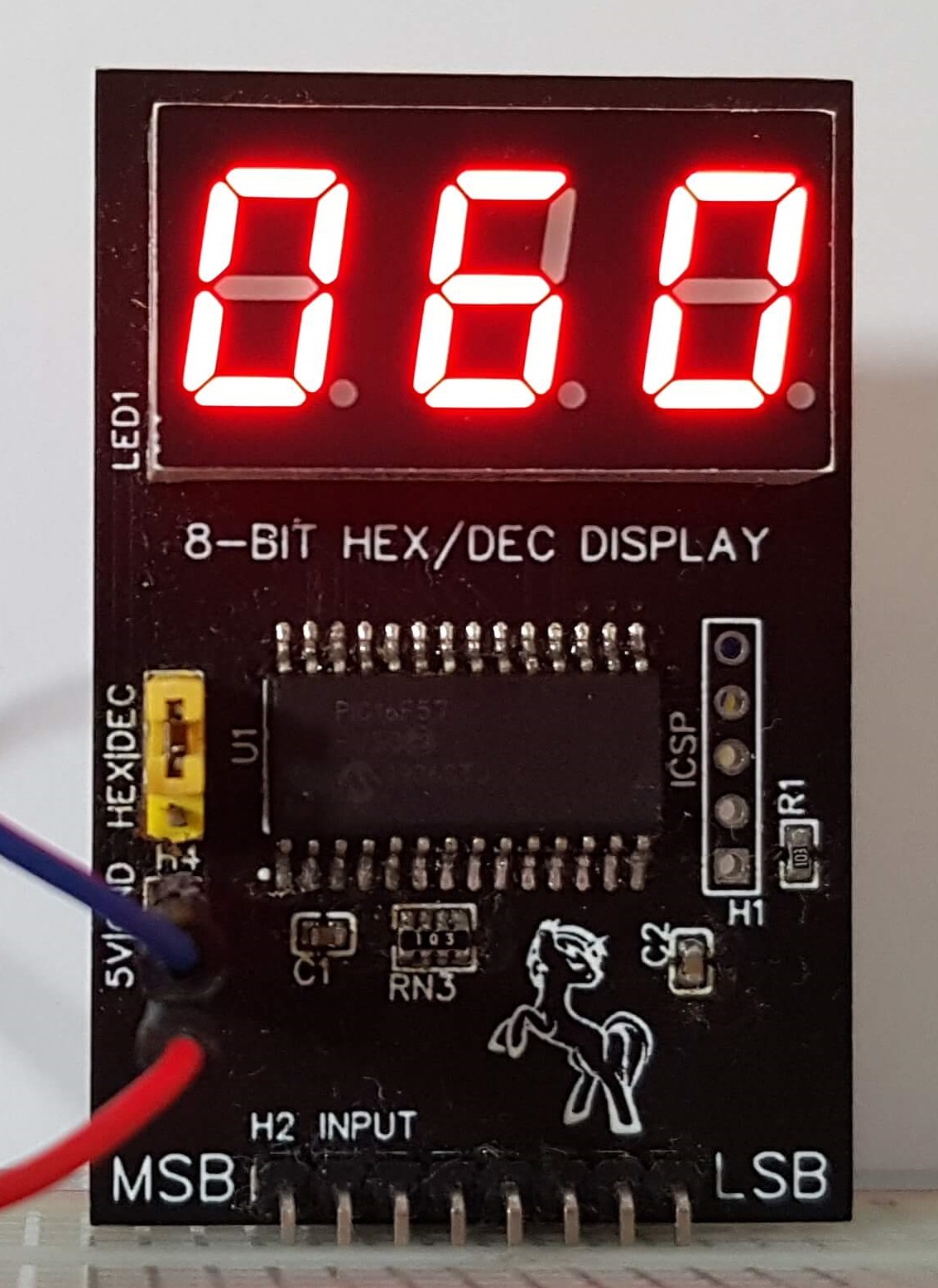
Decimal Display
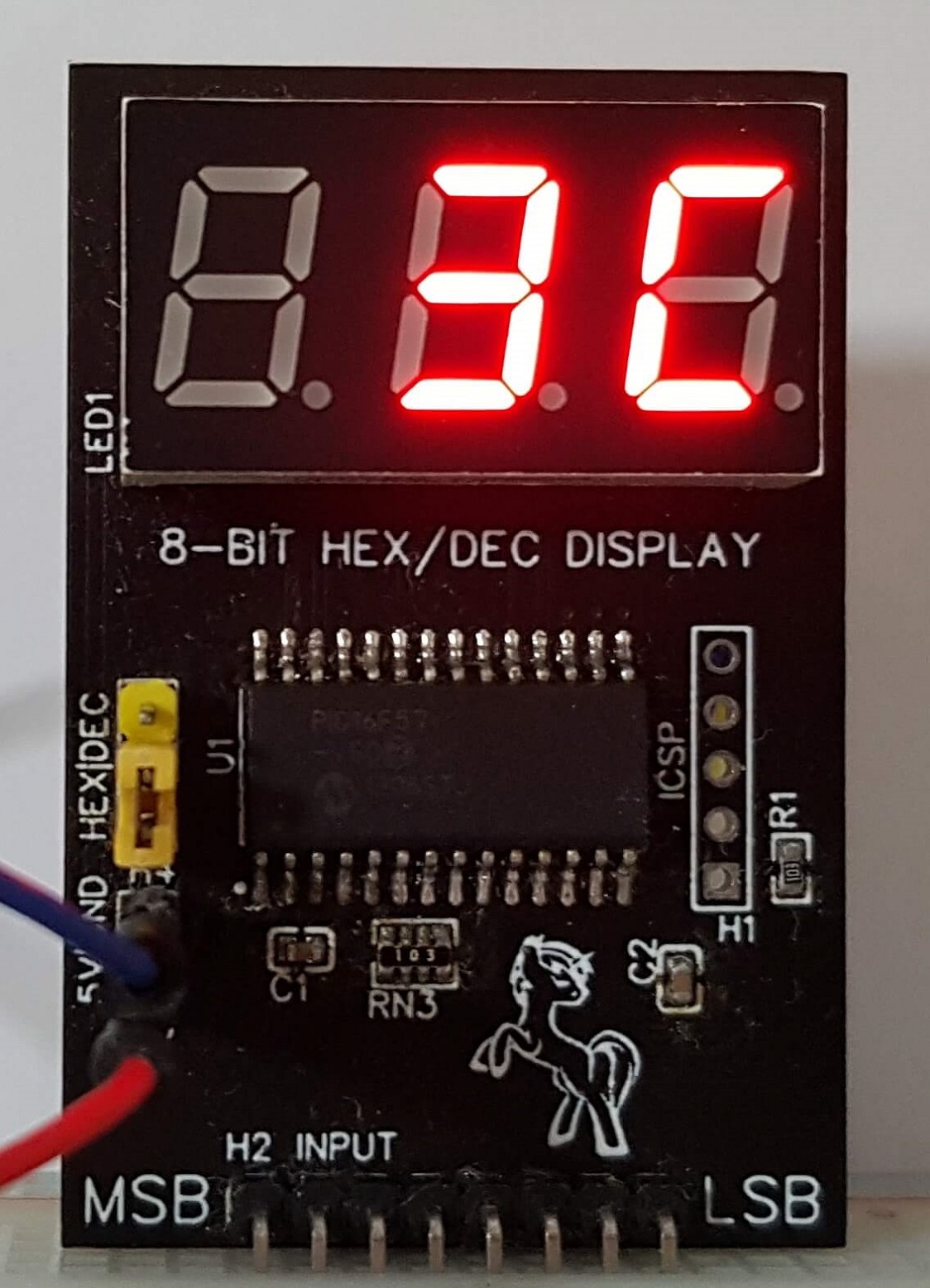
Hexadecimal Display
Very first version designed in EasyEDA. It is powered by a PIC16F57 microcontroller. The signal from the bus is buffered by a 74HCT244 octal line buffer IC. The HCT variant is used for TTL compatibility. The value is constantly sampled and displayed on the display. Hex and Dec could be selected by a jumper.
This version works fine. However there are several pitfalls I came across later that I want to revise:
- The PIC16F57 does not have an internal oscillator and the crystal driver is pretty sensitive.
- The board cannot lie flat because there are several parts on the PCB bottom.
- The 74HCT244 pinout makes it hard to route all the signals.
- Many packages (TSSOP-20, 0603x4, etc.) are hard to solder for beginner. Ends up pretty horrible on my first attempt back then too.
- Parts under the display! More space saving but not beginner friendly.
- No pullup on the Hex/Dec jumper. (Yes, this MCU is so old there are no internal pullups!)
- ICSP header does not work.
Second Revision (May 2021)
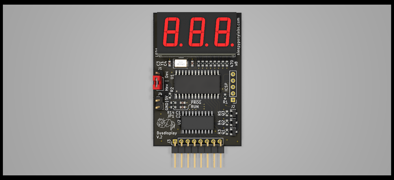
Revision 2 3D render in KiCad
A year later I decided I will try to sell these little boards. Therefore I start a revision work on it. All the issues in the first version are fixed, however there are still some things I did not like in it. Since at this point I realized that the PIC16F57 is no longer the cheapest choice, I decided to scrap this version and move to version 3.
Some details I still don't like, just for reference:
- Still requires an external crystal. 5032 crystal is not that easy to solder.
- Weird jumper configuration requires for the ICSP to work.
- The board size is a little bit too large for a cost-effective PCB panel.
Third Revision (Jun 2021)
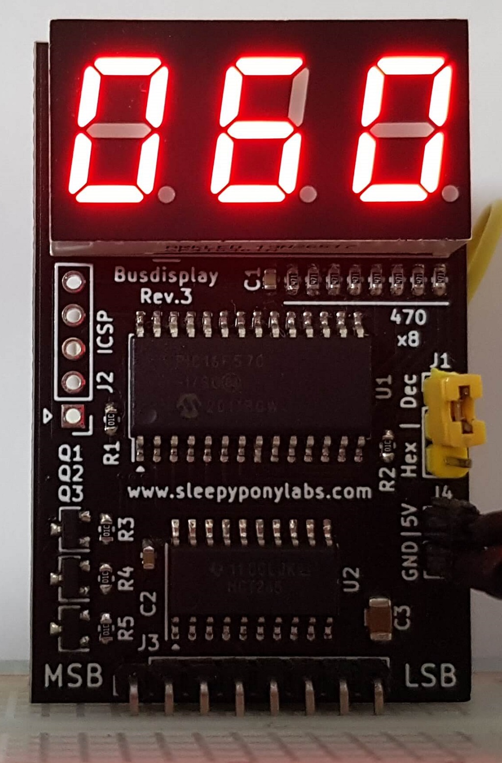
Decimal Display
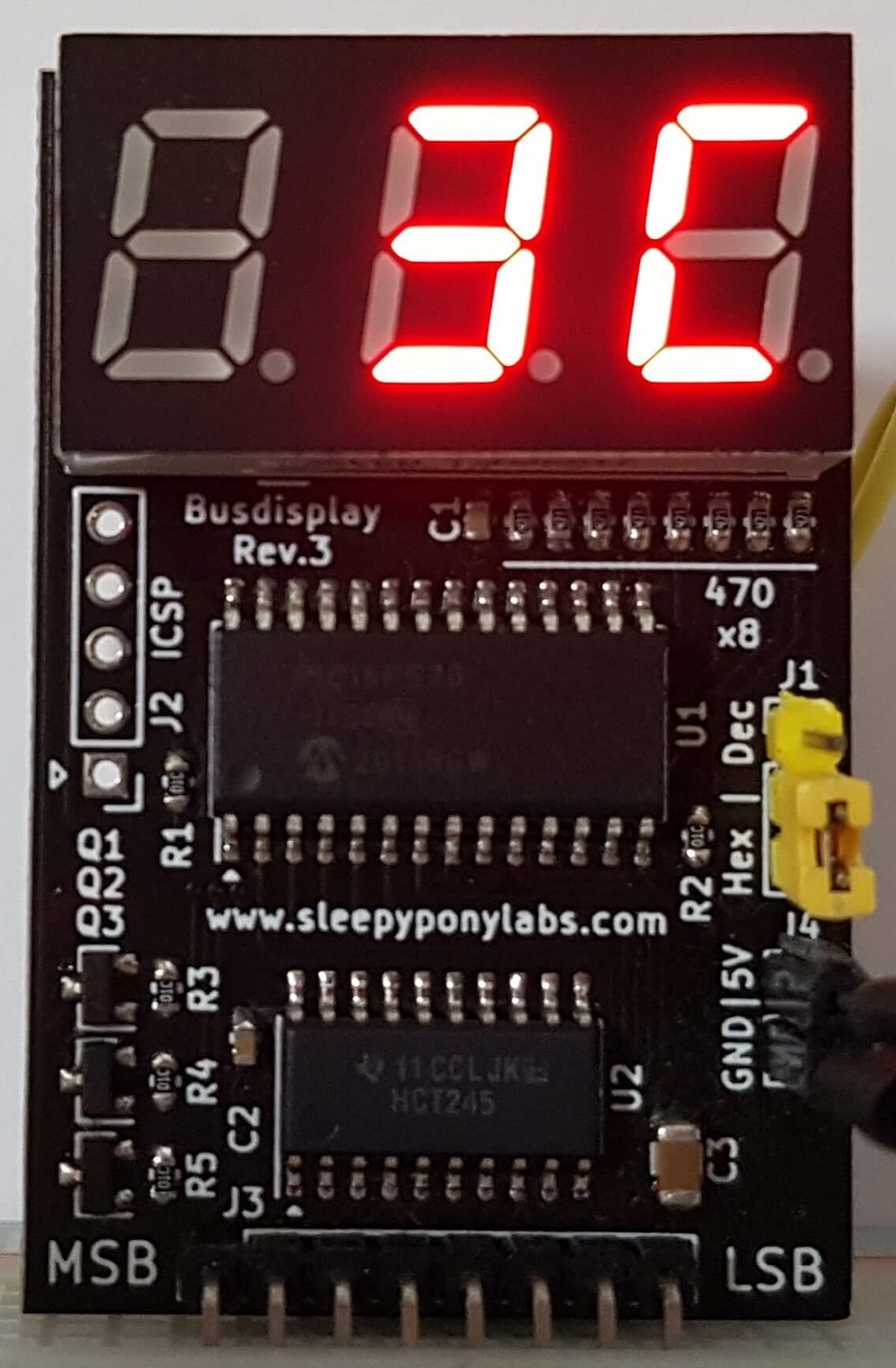
Hexadecimal Display
This is the revision that entered real production. All of the issues and nuisances in both revision 1 and 2 were fixed. I am pretty pleased with how this board turns out and it's quite popular on Tindie because it is cheap.
Improvements made in this version compared to version 1 and 2:
- Change the MCU to PIC16F570. Now cheaper and has internal oscillator.
- Change the buffer chip to 74HCT245 bus transceiver. Much much easier to route and solder.
- Add a bulk capacitor and a pullup resistor for Hex/Dec jumper just in case.
- ICSP no longer has to share its pins with peripherals, so jumpers are no longer needed.
- No longer has parts on the bottom layer or under the display. (The pony is though. :/)
- Replace all hard-to-solder parts for larger and easier ones.
- Resize the board to 33x50 mm. This means the 3x2 panel will fit in the 100x100 mm discount size limit at cheap PCB mfgs, given that there are no edge rails.