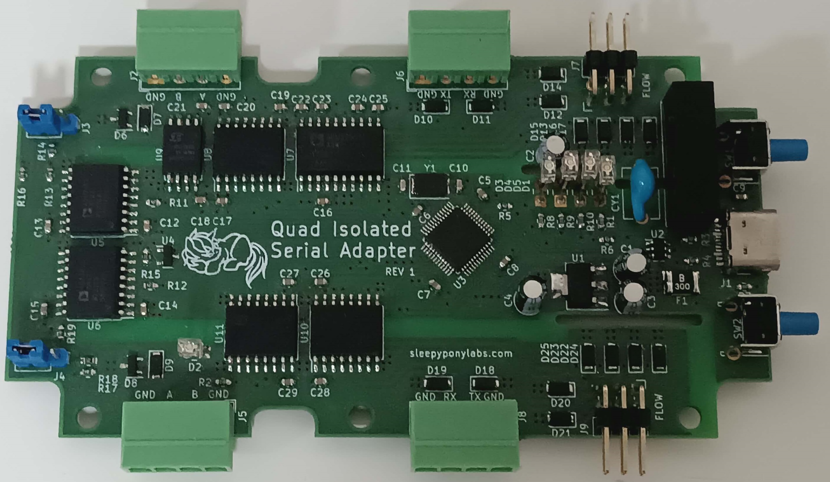
Quad Isolated Serial Adapter
Isolated USB to RS232, RS485, and UART adapter based on WCH CH344Q IC
Background
In 2022, we started working with high-voltage DC systems at work. It did not take long before those HVDC leaked into the USB-to-Serial adapter while debugging the circuit, killing it and the computer. We also found another issue: we don't have enough serial ports. It was common that we need to communicate with 2 or 3 devices at the same time and the 1-channel adapters are hogging up all the USB ports. Those two problems are what inspired me to build this isolated USB-to-serial adapter that contains 4 serial channels.
Apart from some hiccups and bad USB connector soldering jobs, the board works great and is real useful at work. The BOM cost of it is very expensive compared to my other works but I believe they have good value and this is no doubt one of the best PCB I had built up to this point.
Note: The PCB for this project was sponsored by Aisler using the Beautiful Boards HD 4L specifications. You may order this board for yourself at this link.
First Revision (Nov 2022)
Summary of Features
- CH344Q quad-channel USB-to-Serial IC
- Max speed of 6M baud (limited by isolators speed however)
- 1024 bytes of RX FIFO buffer and 512 bytes of TX FIFO buffer per channel
- 2x RS485, 1x RS232, and 1x 5V UART channels
- Auto direction control for RS485 channels
- Full modem signals IO (for RS232 and UART channels)
- RX, TX, and Ready indication LEDs
- Reset button (to reconnect to the computer without removing the cable)
- Isolation between the USB and Serial sides
- ADM2483 dedicated RS485 isolation IC
- ADM3251 dedicated RS232 isolated IC
- Digital Isolator ICs for other signals
- 1W 5V isolated DC/DC converter
- Misc. Features
- USB Type-C Connector with TVS and Fuse protection
- Degson 3.5mm terminal blocks for serial channels
- RS485 120 Ohms termination resistors (can be turned on/off)
- Power indicators on both side of the isolation
- USB reset and flow control mode buttons
- Design to fit a Futurebox FB17 project box
CH344 IC
CH344 is a 4-channel USB-to-Serial IC made by WCH. It is available in two variants: CH344L and CH344Q. The CH344L variant supports VDD of 3.3V-5V and max baud rate of 230400, while the CH344Q variant is more expensive and only supports VDD of 3.3V but the baud rate could go up to 6M and contains more features. This board uses the CH344Q variant for maximum baud rate.
Note: Although both variants use the same LQFP-48 package, they are NOT pin-compatible and works slightly different in some aspects. See the datasheet of both variants to see which one works best for you.
When plugged into the PC, four serial ports would show up as "USB-Enhanced-Serial" A to D, which is connected to serial channel 0 to 3 respectively. WCH also supplies a configuration tool CH34xSerCfg (requires this driver to be installed first) that can be used to set various parameters of the chip such as operation mode, VID/PID, custom device name, etc. I personally did not set anything with the tool but feel free to look around.
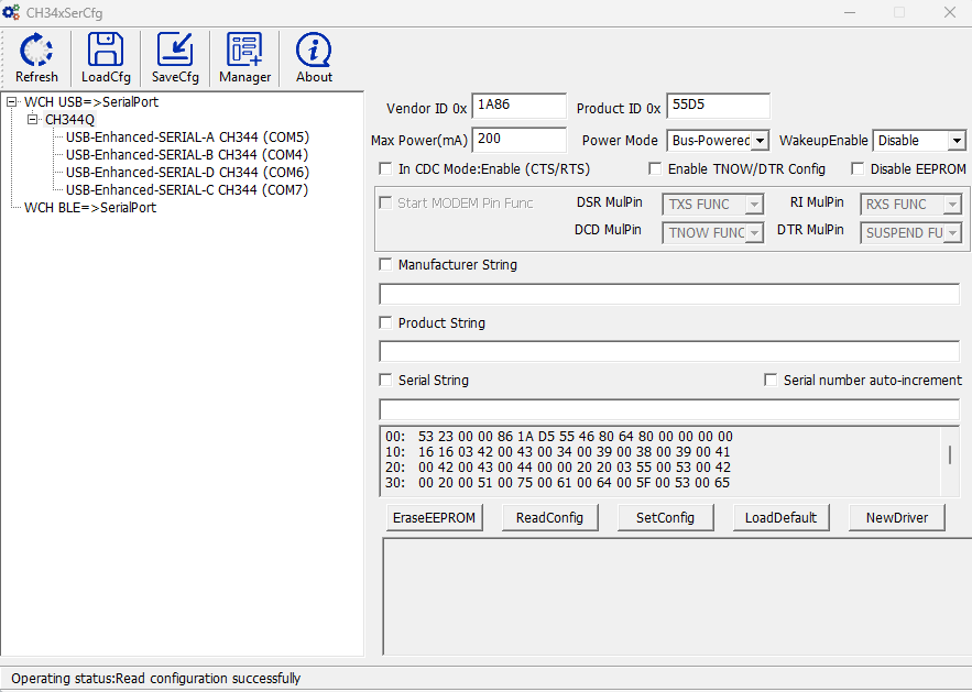
CH34xSerCfg tool by WCH
Digital Isolators
Based on the requirements at the time and the features of the CH344Q, I decided that the adapter will have two RS485 channels, one RS232 channel, and one UART channel. To isolate the USB side and serial port side, we need to use a type of chip called digital isolators. These chips provide galvanic isolation between each side of the chip (usually called side A and B). They could isolate up to 5kV DC so the USB port and computer would be protected. Since the A and B side requires separate power sources they typically works as a logic level translator too, but check the datasheet first.
There are two types of these devices:
- Generic I/O Isolation. Could be use with typical push-pull signals such as UART and modem signals.
- Interface Isolation. They isolate one type of interface only, such as RS485, RS232, CAN, I2C, etc.
ADM2483 - Isolated RS485 Transceiver
ADM2483 is a pretty popular RS485 transceiver chip from Analog Devices. It provides 2.5kV isolation, max 500k baud rate, and 3V-5V support. The usage is straightforward because it's pretty much an isolated version of MAX3485 with slower speed. A single catch of this chip is the PV pin (pin 7). Turns out this chip requires an external voltage supervisor IC to be attached to this pin for the correct POR behavior. The PV pin should be driven low when the A side voltage is below 2V. A cheap 809R or 809Z IC would be enough, but still a bummer.
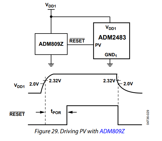
PV pin voltage supervisor circuit (Source: Datasheet)
ADM3251E - Isolated RS232 Transceiver
ADM3251E is one of a few isolated RS232 transceiver chip in the market today. Turns out Analog Devices is the only one making this kind of chip, and this particular one is the only one that is not LGA/BGA and is not too expensive. It provides 2.5kV isolation, max 460k baud rate, and 5V support. Again, it is pretty easy to use, just the typical four 100nF charge pump capacitors like a typical transceiver IC. What's impressive about this chip is that it only requires a single 5V power source. The chip provides its own isolated 5V source on the RS232 side.
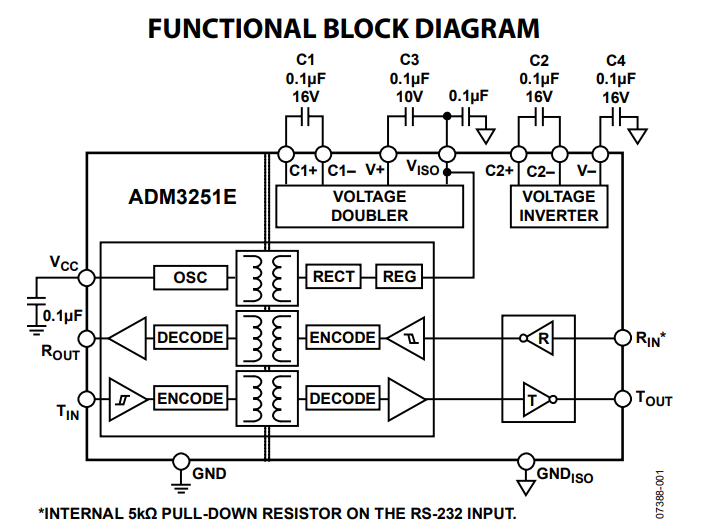
ADM3251E Block Diagram (Source: Datasheet)
CA-IS37xx Series Digital Isolators
CA-IS37xx Series is a generic I/O isolators from Shanghai Chipanalog Microelectronics. This series features 2, 3, 4, or 6 isolation channels per chip and various TX/RX channel count configurations. They provides 3.75kV-5kV isolation, max 150M baud rate, and 2.5V-5V support. You can check out all of their lineup here.
For this board, I use the following chips:
- CA-IS3720HG - 2 channels in one direction only. 5kV Isolation. Use for RS232 modem signals.
- CA-IS3741HW - 4 channels, one are reversed direction. 5kV Isolation. Use for UART isolation.
- CA-IS3742HW - 4 channels, two are reversed direction. 5kV Isolation. Use for UART and RS232 modem signals.
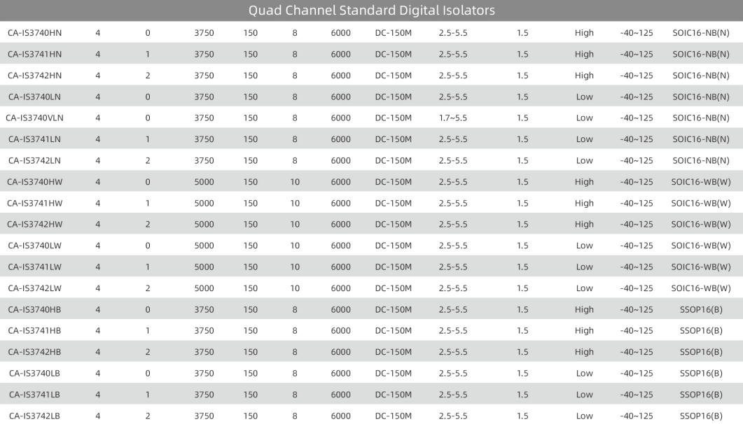
Some CA-IS37xx chips available
Power Isolation
Since we need power supply on the other side of isolation, we need to use power isolation modules. These are tiny black box with isolation transformer inside that could provide around 1-2W of power. On this board I use the B0505 isolator that could provide 1W of power (200mA at 5V).
Although this power module could work by itself, they recommended placing a 1nF Y-class safety capacitor between both ground of the circuit, so I also add that.
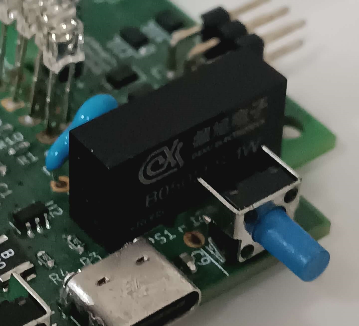
B0505LS-1W Power Module and Y-Class Capacitor on the PCB
Enclosure
This board has been designed to fit in a Future Box FB17 box, which explains the weird shape of the PCB. The board fits perfectly. The problem is that I will have to cut the holes for connectors, LEDs, and switches myself. I don't really have tools or time to do that so it remains without an enclosure for now.
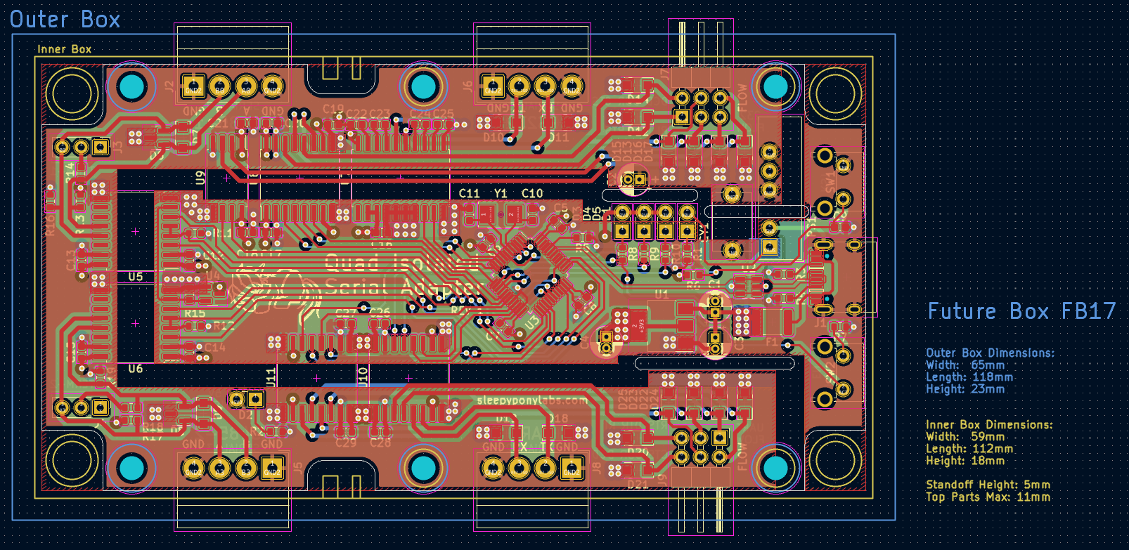
How the PCB was designed around the FB17 box in KiCad
Points for Improvement
- The footprint of U9 (CA-IS3720HG) is incorrect. SOIC-8W is wider than other wide SOIC footprints. I should have used KiCad footprint...
- Add voltage selection for UART. Chipanalog chips could work down to 2.5V anyway.
- Change the enclosure to one with pre-cut holes.