Super Expander
What if a microcontroller has 512 I/O Pins?
Background
The idea for this funny board came up back when JLCPCB had just released their 4L PCB service. Being curious pony, I really want to try this out. One problem is that I had no projects coming up yet. After a quick trip to LCSC and stuff I came up with this board as an excuse. We will go into details later as to how bonkers this board is.
Note: The Chinese chip I used on this board (AW9523BTQR) now has the status of NRND (Not Recommended for New Designs). At the time of writing (15 Mar 2023) there are still around 11k pieces left on LCSC. If you are interested in doing something with this chip, you better order now!
First Revision (May 2022)
Demo video of the board in output mode, outputting logic high.
General Idea
My design goal of this project is to extend the microcontroller pins out as much as possible, while conforming to JLCPCB promotional price size limitation of 100x100mm. As this is just a silly project I also don't want total BOM cost to be overly expensive as well.
Browsing through LCSC, I realized that there is one interesting chip out there that will fit the purpose: AW9523BTQR I/O Expander IC, which makes the whole thing possible.
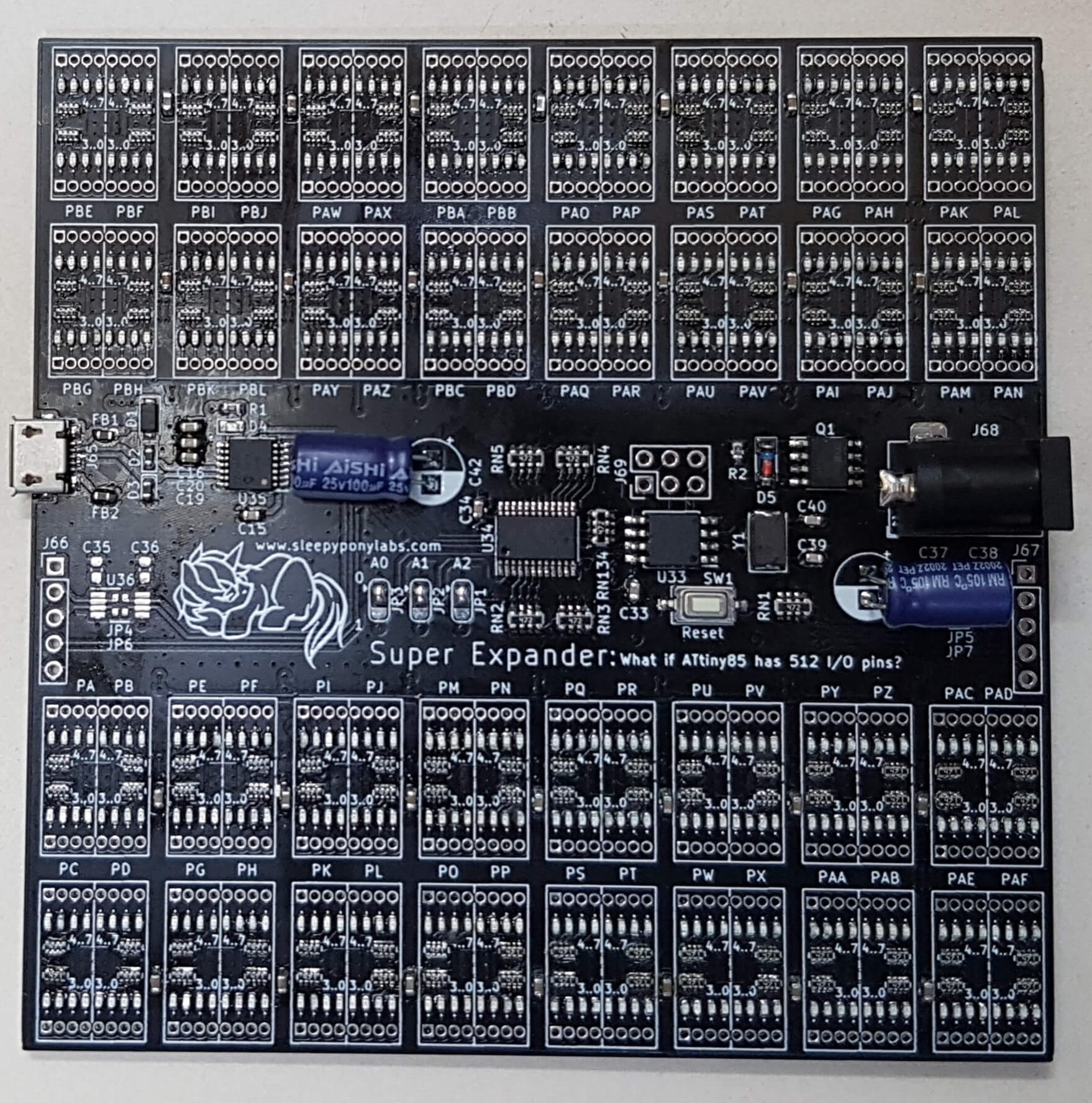
After some long hours, I got a set of 512 I/O pins to fit on a 100x100mm PCB. The board features:
- 32 AW9523BTQR I/O Expander chips, in eight group of four chips.
- 512 LEDs on each I/O pin. (Unfortunately not in the sink direction.)
- PCA9548A 8-Channel I2C Switch IC, to split a single MCU I2C bus into eight.
- MCP2221A USB-to-I2C chip, for direct control of the board from a computer.
- 2 TCA9517 I2C buffer, for connecting multiple boards together.
- ATtiny85 microcontroller
- Power input and reverse voltage protection circuit.
AW9523BTQR - Explained
AW9523BTQR is a 16-bit I/O Expander IC made by Shanghai Awinic Technology. Its 16 pins are divided into two 8-bit ports which are controlled through I2C. With two address select pins you can connect up to 4 chips on the same I2C bus.
Each pin is capable of input, output, and constant current sink. The constant current sink feature is pretty unique and is not available on other popular chips. You can separately dim LEDs connected to each pin separately in 256 steps. Each channel can sink maximum of 20mA which is plenty for many usages.
The chip also features pin change interrupt on input channels: you can set which pin will cause an interrupt, and then if any of the pin changes its level the interrupt signal will be sent on the INTN pin. (Similar to how PCINT works in ATmega328P.)
There is a caveat though. This chip has a weird POR (Power On Reset i.e. what would the chip do after powering up) behavior. The pin direction settings and output levels depend on the I2C address you choose through AD0/AD1 pins! This table is provided in the datasheet to indicate what would happen, but it is still a big pitfall because this is so unique. Your circuit might need to be in some certain state on startup and you will have to design around the expander.
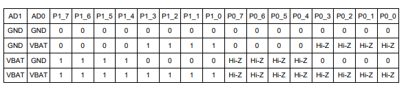
The POR behavior table based on I2C address (Source: Datasheet)
The chips are placed onto 8 I2C buses, each with 4 chips (AD0/AD1 pins give 4 address options). Therefore one "bank" of GPIOs consists of eight 8-bit port, for a total of 64 GPIOs on multiple 1.27mm pin headers. Each GPIO pin has its own indicator LED. Unfortunately I put them in source configuration instead of sink, which means I cannot use the constant current mode. This mistake is due to confusion while looking at the POR table above, making me think I can only use CC mode if the I2C address is 0.
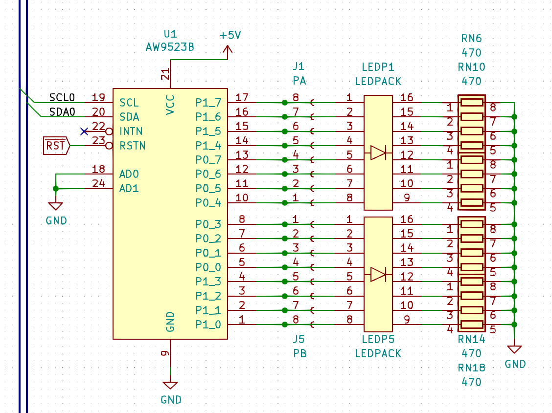
A circuit for each AW9523BTQR chip
PCA9548A and TCA9517 - We need more I2C buses!
So now we have all the GPIOs wired up, but we still need to figure the I2C side out. Most typical microcontrollers have only 1 or 2 I2C peripherals available and we need 8. PCA9548A is a chip we need. This neat 8-Channel I2C switch allows us to connect a single I2C bus from our microcontroller to up to 8 other I2C channels, one or more at a time (you do need to observe maximum bus capacitance and collision though).
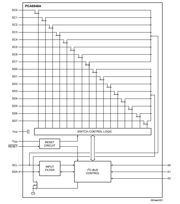
PCA9548A Block Diagram (Source: Datasheet)
Controlling this chip is simple. The chip has its own I2C address you need to address. Then after an ACK from the chip, you send a single byte indicating which line to connect. You can also read the selection back from the chip by calling to its read address. To reset the chip and deselects all the channels, set its RESET pin to low.
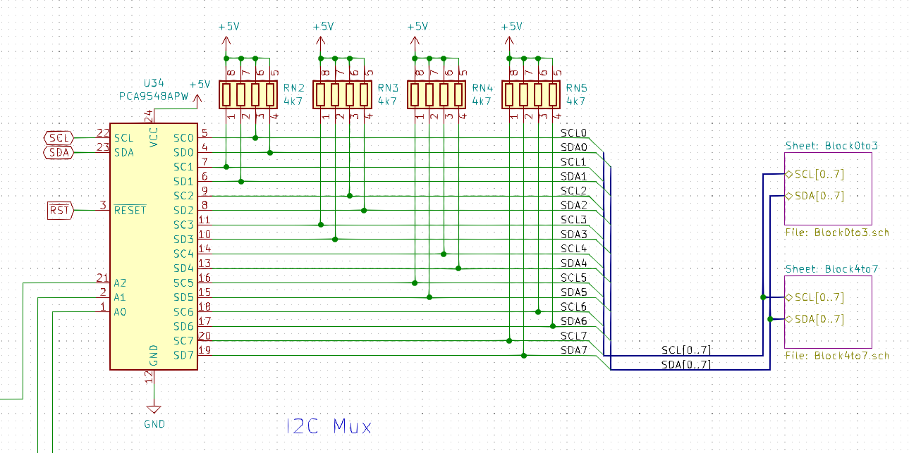
I2C Multiplexer circuit (address jumpers not shown)
Now we got all 8 buses we need, but we're not done yet. PCA9548A also features three address selection pins (A0-A2), therefore we can connect up to 8 of these chips together! I've then decided to include some headers on the side of the board to connect multiple of them together. However, I2C cannot be dragged very long. Its intended use is for short-range communications anyway. We need additional chip to allow multiple boards to connect reliably.
Note: The I2C buffer circuit is never tested. I cannot tell with certainty if this chip is needed or not or if it is appropriate for this application. Please use your own judgment.
Entering TCA9517 Level-Shifting I2C Buffer. This chip allows the I2C bus to be extended further while maintaining the bus capacitance. Its Level-Shifting feature allows both side of the I2C signal to operate at different voltages (between 0.9-5.5V and 2.7-5.5V).
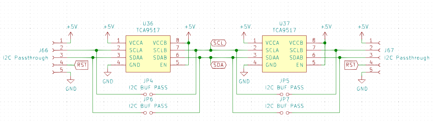
TCA9517 repeater circuits for board cascading (untested)
To sum it all up, we can connect 8 of these boards together and set different address for PCA9548A on each one. Making the hypothetical maximum amount of GPIOs to be 4096 (!!!) which is probably not practical but fun to think about.
The microcontroller
On this board I put a single ATtiny85 on it as a microcontroller. As to why I select it, it's just a jellybean part for me back then and it does have a peripheral called USI (Universal Serial Interface) that looks good enough for I2C. I regretted this decision a lot.
First, USI is a very bare bone serial peripheral. It only has a byte of data register, a byte of buffer, some start/stop conditions detection, and some additional controls. It can't even generate its own clock signal. After reading on many forum posts about USI I still have no idea how to use it for I2C. At this point even ancient PIC12 seems to have better-sounding implementation of I2C.
Second, the pinout of ATtiny85 is of typical old Atmel style: GND at the bottom left and VDD at the top right, like a logic chip. This means I cannot put any of the newer chip in the Microchip era (with proper peripherals) on the existing PCB because Microchip style puts GND at the last pin (i.e. pin 8) and VDD at pin 1.
In conclusion, I'm stuck unable to do anything to the board unless I spin up a new batch of boards with different microcontroller (which will need a major overhaul because the AW9523BTQR is now NRND), or figure out how to get USI to do I2C for me. Luckily I still could control the board to some degree due to the existence of the USB-to-I2C chip on the PCB.
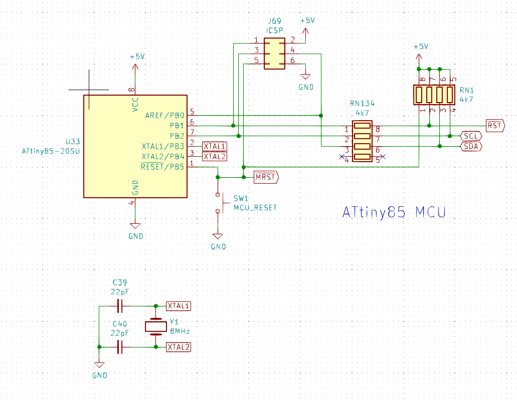
ATtiny85 Circuit. The resistors are in place so the ICSP will not be interfered by the I2C device.
MCP2221A - Controlling I2C Directly from a Computer
MCP2221A is a USB-to-I2C bridge IC, an upgrade of the old MCP2221 with higher maximum baud rate of 460800. This chip allows the computer to directly connect to any I2C devices (plus four GPIOs and a UART) and acts as a USB CDC or HID class device to a computer. Microchip provides both configuration utility for setting the chip up and control software/library to interface it with your own application. I've tried both of these and they are actually really useful. The demo video above is created by me sending I2C commands from my computer using Microchip's MCP2221 CLI.
To check out more about the tools and libraries available, see the official product page. There are quite a lot of details that I will not be able to fully describe here.
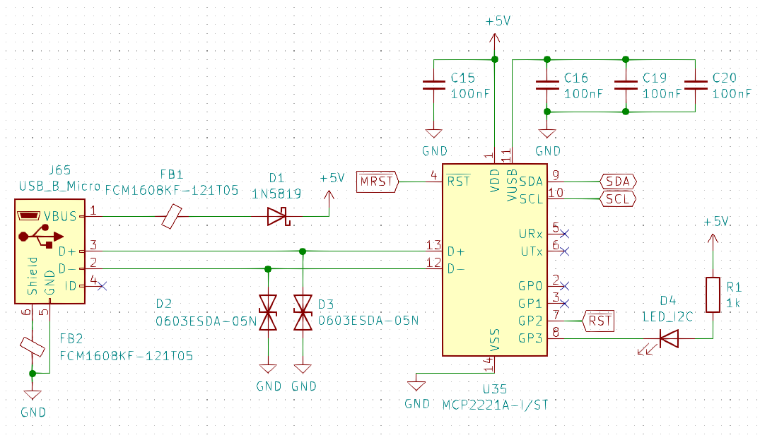
MCP2221A Circuit. GPIO3 is an activity indicator, and GPIO2 is used to control the reset signal.
Some Afterthoughts
Apart from the circuit itself, there are also other things to talk about. This board may be made just for fun, but it had given me quite a lot of experiences such as:
- Designing and ordering a 4-layer board from JLCPCB. (They are offering 8L for 2$ now. What a time to be alive.)
- Designing with new class of chips: I2C switch and repeater.
- Soldering with solder paste and a hot air gun. (First project that I use my soldering station to assemble.)
- Soldering parts smaller than 0603: 0402 and 0402x4.
- Soldering leadless QFN parts with a hot air gun.
Points for Improvement
As I already stated above, the I/O expander chip I used for this board is now NRND. The most obvious thing I need to do (if there's still interest in this experiment board) is to find a replacement chip with similar price (30 cents each at 30 pcs) and functionality. Unfortunately, this chip is one of the cheapest of the kind, and most of other chips with similar price point are either PCF8574 clones or 8 GPIOs devices, and none has the constant current functionality similar to the old chip. Here are some examples of what I could find on LCSC:
- CH423S: A classic from WCH. Has 8 GPIOs and 16 sink-only inputs. The only one that is cheaper than the old chip.
- PCA9555: Do have 16 GPIOs. Clones are around x2 the price of the old chip and the NXP chip is x4.
- PCA9557: Have 8 GPIOs without anything much to talk about. Half the price of PCA9555.
- PI4IOE5V6408: An obscure Diodes/Pericom chip. 8 GPIOs with voltage translation. Price is similar to PCA9555.