TLC59025 Devboard
A devboard for TI TLC59025 Constant-Current LED Sink Driver IC and clones
Background
I had an idea about building sort of LED light board for train maps. This kind of project would required a lot of individual LEDs to be driven. At first, I thought I will use the ISSI (now Lumissil) IS31FL3236A 36-Channel PWM LED driver chip for it. However, since this chip use I2C for communication and limited options for address selection, controlling a lot of these driver will be tricky. A new chip is needed.
After some digging on LCSC, I found a new chip which is the Macroblock MBI5124GP. This chip is interesting, because it is very easy to control and cascade via SPI (or to be honest, like a typical shift register), very cheap, and could control 16 LED.
With some help from Greg Davill on Discord, he pointed out that this chip (and many more) are actually a clone of Texas Instruments TLC59025. At this point I really do want to use this chip for the train map so I decided to build a devboard for it just to see what it could do.
Note: I misspelled the chip name. You might see the naming "TL59025" in various locations. This is a typo.
Note: The PCB for this project was sponsored by Aisler using the Beautiful Boards Budget specifications. You may order this board for yourself at this link.
First Revision (Sep 2022)
Demo video of three devboards running LED chaser program
The Chip (and its clones)
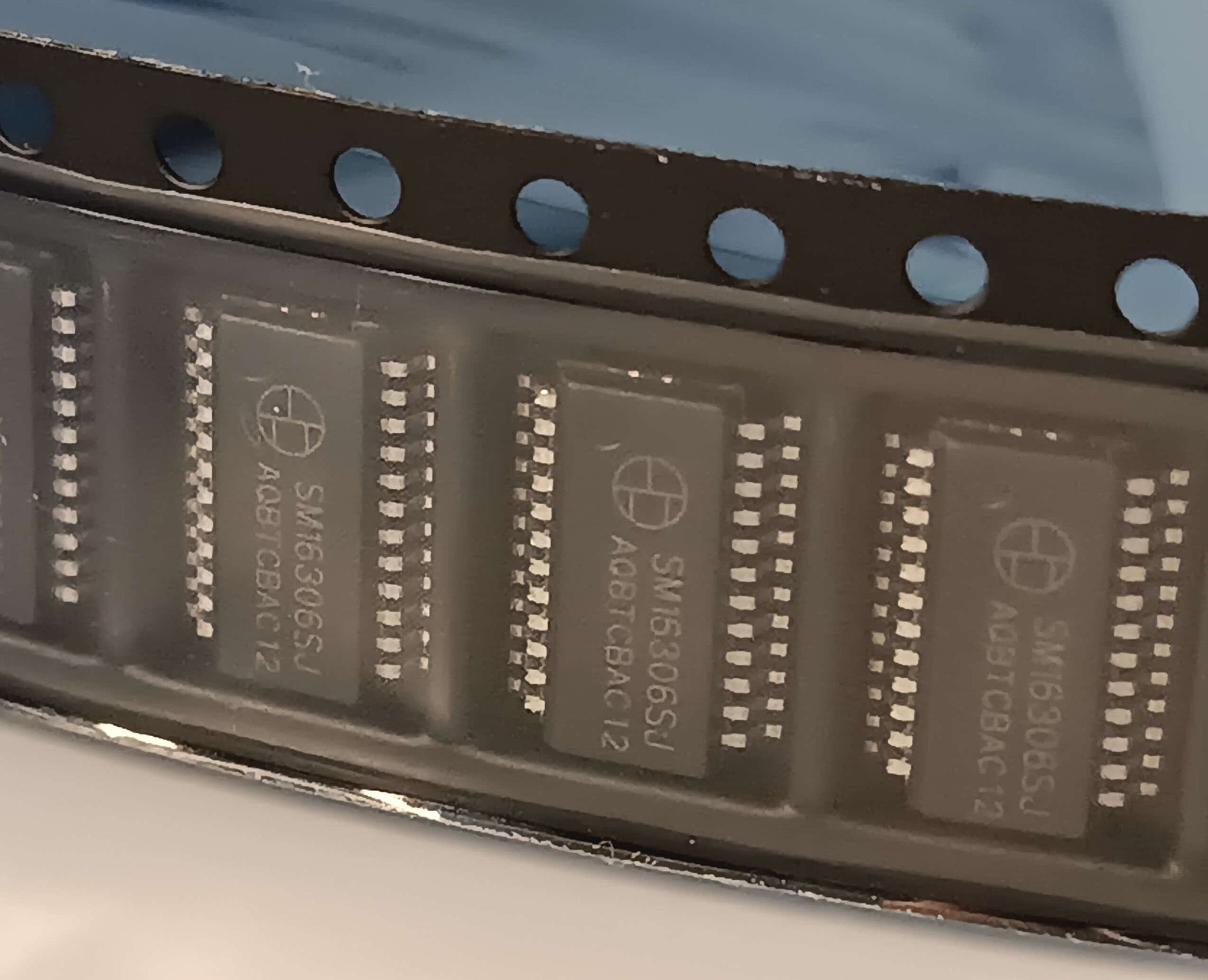
Shenzhen Sunmoon Micro SM16306S
TLC59025 has a lot of clones. These cheap clones are popular in LED video wall applications. Some clones available on LCSC are listed here. Noted that I will only list the ones with QSOP-24 package that is compatible with this devboard. Other variants might exists.
- Texas Instruments TLC59025 (original) Datasheet
- Macroblock MBI5124GP-B Datasheet
- Shenzhen Sunmoon Micro SM16206S Datasheet
- Shenzhen Sunmoon Micro SM16306S Datasheet
- Shenzhen Titan Micro TM5020A Datasheet
Note: I use SM16306S clones on the demo boards as the original chip is not available on LCSC.
TLC59025 has a lot of cool features. For example:
- 16 Constant-Current LED Sink Drivers
- Adjustable output current
- Works like a shift register. (Just like two 74HC595 in cascade.)
- Can cascade with more chips. (Again, like a 74HC595.)
- SPI Compatible
- Very cheap. Clones are like 5 cents apiece in larger quantities.
- Easy to place and route on the PCB.
The LED output circuit
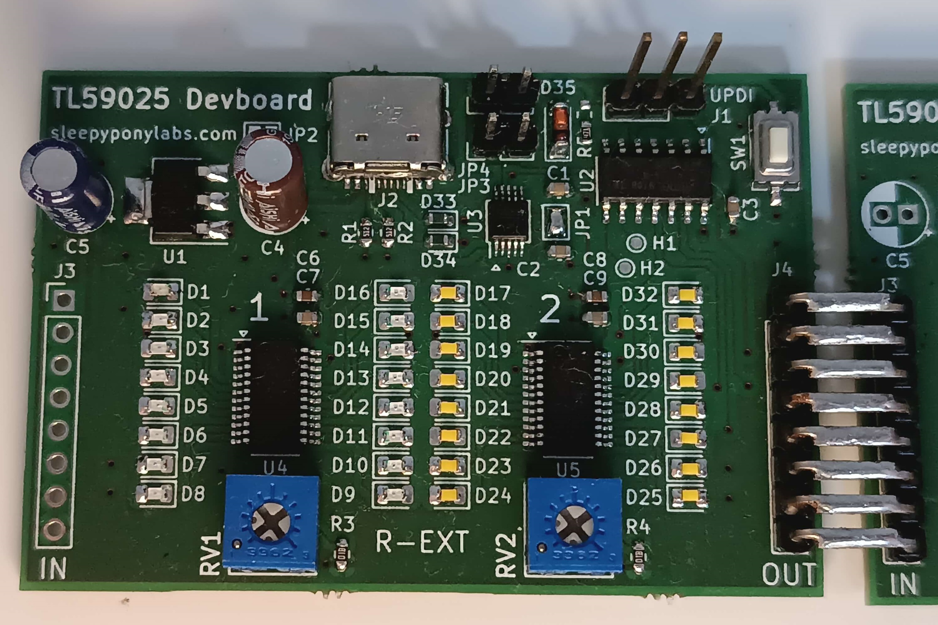
The devboard features spots for two TLC59025 chips in a cascade configuration, for a total of 32 LEDs per board. (The clock (CLK), latch enable (LE), and output enable (~OE) select signals are in common.) To support further cascading, the cascade in/out headers are also provided. The regulated and unregulated power are also present on the header so you only need to connect your power supply on a single board.
Apart from the decoupling capacitors, the chip only requires one single additional component: the R-EXT resistor. This resistor sets the target amount of current to sink from each output channel. Surprisingly this is the part where it gets tricky. Turns out each version of the chip comes with different formula to calculate the output current. Generally, to get the maximum output current you need 500 Ohms, and you leave the pin floating for minimum current. Be sure to check your datasheet! The devboard allows for a minimum of 510 Ohms of R-EXT and a 10k Ohms trimpot for each chip so you can set the output current based on the LED types and colors.
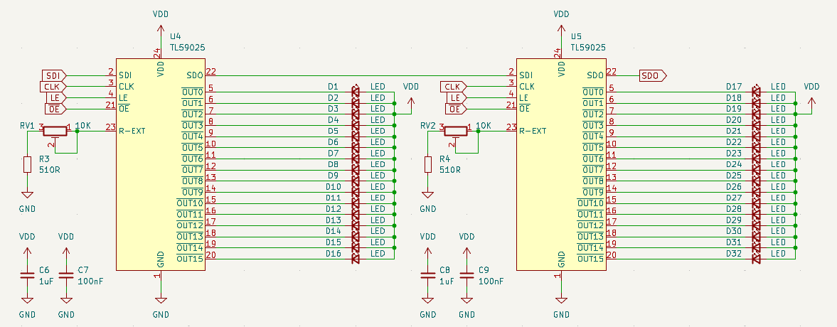
The LED output circuit, with 2 drivers and 32 LEDs
The control circuit
There aren't much to talk about here. An AMS1117 LDO, and a spot for an ATtiny414 microcontroller on the board. The MCU is connected to the driver chips through SPI (remember these are just glorified shift registers!). Some pads and a button are broken out in case you need them, and an UPDI header for programming.
I also put a CH340 USB-to-Serial chip on the board. You can use it to send/receive commands through serial port, upload an Arduino sketch alongside a bootloader, or use SerialUPDI to upload your firmware. Here is a quick link to MegaTinyCore on GitHub if you want to learn more about how to use Arduino and SerialUPDI with this MCU and other similar ones.
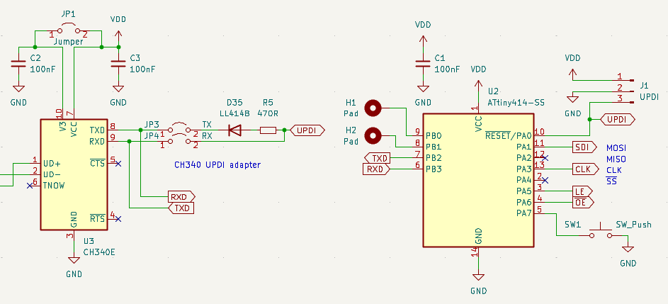
Part of the control circuit: a single ATtiny414 and supporting circuits